Difference between revisions of "Logic"
From #openttdcoop wiki
(→Advanced logic elements) |
|||
| Line 30: | Line 30: | ||
== Advanced logic elements == | == Advanced logic elements == | ||
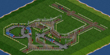
| − | [[File:XOR.png|thumb|220px| | + | [[File:XOR.png|thumb|220px|left|XOR construction, you can see the OR and NOT gate inside]] |
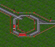
| + | [[File:Edge_detector_falling_inverted.png|thumb|220px|right|Falling edge detector (inverted). Output (right) flashes green when input (left) changes from red to green.]] | ||
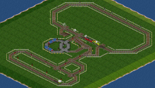
| + | [[File:Logic traincounter.png|thumb|220px|left|A simple train counter. It can fail if the line jams. The counter train (lower left part) is released if the TL2-train blocks the NOT gate entry, but not the signal block behind and in front of it.]] | ||
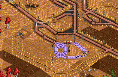
| + | [[File:Logic traincounter.png|thumb|220px|right|A delay circuit. When the input (top right) turns green, after the train traverses the loop the output (bottom left) will flash green. The delay depends on the speed of the train.]] | ||
=== XOR === | === XOR === | ||
XOR gates are red if exactly one of its two inputs is red. There is no known elementary gate for this, but it can be built as combination of multiple gates: (A XOR B) = (A OR B) AND (NOT(A AND B)) where A and B are the inputs. | XOR gates are red if exactly one of its two inputs is red. There is no known elementary gate for this, but it can be built as combination of multiple gates: (A XOR B) = (A OR B) AND (NOT(A AND B)) where A and B are the inputs. | ||
| − | |||
=== Edge detector === | === Edge detector === | ||
An edge detector is sensitive to ''changes'' of its input: If the input switches from red to green (or green to red, depending on the implementation), its output becomes green (or red) for some time, and switches back to its original position afterwards. This can be used to detect trains running on a line. | An edge detector is sensitive to ''changes'' of its input: If the input switches from red to green (or green to red, depending on the implementation), its output becomes green (or red) for some time, and switches back to its original position afterwards. This can be used to detect trains running on a line. | ||
| − | |||
=== Basic train counter === | === Basic train counter === | ||
A train, running in a loop, can be used as counter: Most of the time, all signals for this train are red. To count up, all signals get green for a short time, and the train travels to the next signal. This can be used to store data, for example in [[Self-regulating Network|self-regulating networks]]. | A train, running in a loop, can be used as counter: Most of the time, all signals for this train are red. To count up, all signals get green for a short time, and the train travels to the next signal. This can be used to store data, for example in [[Self-regulating Network|self-regulating networks]]. | ||
Revision as of 21:08, 27 August 2019
OpenTTD allows to control trains with signals. The introduction of presignals allows to build more complex setups - the state of a signal (green/red) does not only depend on the following signal block, but also on other signals. For details, see the signal-article in the OpenTTD wiki [1].
Presignals are frequently used to control trains in priorities and station entries. The combination with dummy trains, however, allows even more powerful constructions. Signals can be green or red, those states can be identified with 0 and 1, respectively (this is just a convention, it could be used the other way round as well). With trains and signals, it is possible to build all basic computer elements. In theory, it is possible to build a CPU in a game. You could even simulate OpenTTD in OpenTTD, if map size and computing power would not be a limit.
To keep constructions simple, most logic constructions are built out of several standard elements, called gates. Usually, those gates are separated with combo signals to avoid unplanned influences. If the setup is sensitive to the timing (train A has to arrive before train B or similar), this has to be taken into account in the design. Otherwise, logic gates can be combined in arbitrary way to get the desired output (green/red signals) based on some input (usually: train positions).
Contents
Logic gates
There are always many ways to build gates. The constructions shown here are the most simple setups - if space is limited, it is often useful to change their shape a bit.
NOT
The most common logic gate you will see on coop servers is the NOT gate. It inverts the input: If the input is green, the result is red, if the input is red the result is green. This is done with two trains running on a 3x3-tile ring. If the input is green, they keep moving and at least one train keeps the output red. If the input is red, both trains stop behind an entry signal and the output is green. It is possible to use TL0.5-trains (single engine), but the gates work better with TL1-trains (two engines or double engine).
AND
AND gates are red if and only if all inputs are red. This is a feature of presignals - an entry or combo signal is red if all exit and combo signals leading to that block are red. There is no (practical) limit on the number of inputs.
OR
OR gates are red if and only if at least one input is red. There are two ways to implement this: An OR gate or a construction similar to a priority. The latter method requires less space, but it works only with trains in that signal block itself - you cannot combine arbitrary logic lines like that.
Advanced logic elements
XOR
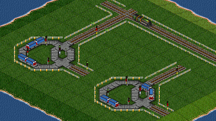
XOR gates are red if exactly one of its two inputs is red. There is no known elementary gate for this, but it can be built as combination of multiple gates: (A XOR B) = (A OR B) AND (NOT(A AND B)) where A and B are the inputs.
Edge detector
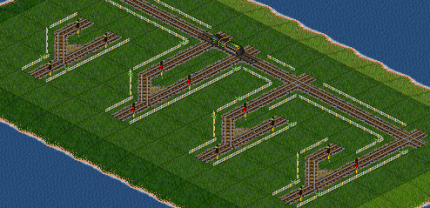
An edge detector is sensitive to changes of its input: If the input switches from red to green (or green to red, depending on the implementation), its output becomes green (or red) for some time, and switches back to its original position afterwards. This can be used to detect trains running on a line.
Basic train counter
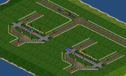
A train, running in a loop, can be used as counter: Most of the time, all signals for this train are red. To count up, all signals get green for a short time, and the train travels to the next signal. This can be used to store data, for example in self-regulating networks.
Delay
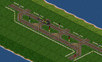
A delay has the same output as its input, but it needs some (usually fixed) time to change the output. This can be useful if timing is important.
Red -> absolute red
A special gate to produce absolute red: A train in a signal block instead of a red presignal.
Clocks
Clocks are used to track time, for example time after the last train went through a line. See Mark's clock for an example. A very simple clock can be built with a train and a timetable to stay in a station for x days.
Applications
SRNW stations
Stations in self-regulating networks are the most common application of logic. The trains themself cannot have a full load order, therefore it is required to control that with logic. Usually, this is done with dummy or feeder trains - they have a full load order, and SRNW trains are allowed to go into a station only if a feeder/dummy train is unloading there.
There are many possible layouts for SRNW stations, some of them are collected in the Junctionary.
Flipflop-Split
A flipflop is a small memory with two possible states. This allows splits where exactly 50% of the trains go to one side and 50% go to the other side: The flipflop stores the direction of the last train and directs the new train to the other side.
Forced Split
If trains are lost, their destination at a split can be unpredictable. With a red twoway signal, they can be forced to split in a specific direction.
